
 换一换
换一换 


This guide will describe basic and intermediate logic design concepts in an approachable format. It won't cover more advanced topics, but it aims to give a workable understanding of logic design so you can apply these ideas to solving automation problems within Oxygen Not Included. Binary Systems Automation wires carry a binary signal. It only has two states, off and on. All sensors in oxygen not included also give their output as a binary signal. In-game, the sensor's state can be seen to either be active or standby. Active (on) is green and standby (off) is red. Most people would associate active with 1 in binary and standby with 0, this is called active-high logic; however, active-low logic is also useful sometimes. Active-low connects active with a 0, and standby with a 1. All sensors in the game default to active-high configuration, but can be changed to active low in two ways. A) using a not gate (also called an inverter) will change the output, and B) changing the sensor's activation setting to it's opposite will accomplish the same task. For example: If you have a hydro sensor set to "above" 500g, then it will default to active-high and be active when its tile contains 500g or more liquid. It will be in standby (off) when it has less than 500g of liquid. So it's a 1 if it's more, and a 0 if it's less. If you change the setting to "below", the output is basically the opposite of what it would normally be. It will be a 1 if it's less, and a 0 if it's more. This would be considered "active-low" if the condition was really measuring whether it was full or not, though the terms themselves are pretty much irrelevant. The important thing is understanding which one you're using. You can set it up so that it either A) Turn on when full, or B) Turn off when full. The confusing part is that "Turn off when full" means the same thing as "Turn on when not full". So you might use this to control a pump that's pumping into a chamber. It's also important to realize that sometimes things that seem the same aren't. "Turn on when not full" does not mean the same as "Turn on when empty". Lastly, most devices in the game also follow active-high logic by default. So a pump will be turned on when it is supplied with an "active" green signal. Doors are active open and locked when passed a 0. A gas shutoff will shut off flow when passed a 1. In this way they actually feel more like an active-low, essentially gas flows when the input is low, and is blocked when the input is high. The power shutoff is the opposite, it passes power (enabling the circuit) when it is sent a 1, and breaks the circuit when sent a 0. If you're unsure, a simple test will reveal the answer. Diagramming and Planning Creating diagrams, truth tables, and state machine flow charts can really help simplify the design process. It lets you tackle several small problems one at a time rather than just looking at an overly complex giant problem and scratching your head. Well go over each of these tools, and how they can help. State machines will be discussed seperately. Diagramming is very useful. Each logic gate has its own symbol, and using a simple drawing may make it easier to see how things should/could be connected. Pen and paper is handy to use, but there are also websites you can use as well. https://simulator.io/ can be used for diagramming, but it can also be used for easy testing. There are lots of others, and also some free apps on the google play store. Making changes in these tools is much easier than doing it in game, so they can speed up design considerably. Truth tables are almost fundamental. In fact, they should usually be the first thing you do when designing a new circuit. You should think "what do i need this circuit to do?", "what are my inputs?", "what are my outputs?", and "What are the key combinations of inputs and outputs?" As part of this guide I will be creating a water purifier as a follow-along project, and we will likely refer back to our truth tables more than once. Notation Across the internet you can find many different circuit designs and such. In any conversation where people discuss logic you might see some things that may not make much sense at first. There are a few conventions, but as with anything no rules are absolute. Outputs The outputs of a circuit are usually denoted Q, X, or less frequently O. Inputs Inputs are usually denoted A, B, C, etc, but can really be whatever you like. Operators Often you will see a shorthand used to make it easier to write logic statements, these make use of "operators" which are symbolic representations of logic gates. The symbols chosen are chosen for a reason, and may make sense if you've studied boolean math and/or set math. AND is related to multiplication (or intersection if you're talking about sets), and is usually denoted by *, ^, or &. OR is related to addition (or union in set terms) and is usually denoted by +, U, u, V, or v. NOT is pure negation (with a not gate), and is usually denoted by -, !, or with a bar over the top of the thing being negated. = is typically used to denote assignment. Q=A*B The output is given by combining A and B through an AND gate. It could be read as "Q is A AND B" Q=A+!B or Q=A+-B The output is given by combining A and the opposite of B through an OR gate. It could be read as "Q is A OR NOT B" Logic Gates Each logic circuit will be made up of groupings of logic gates designed to combine inputs in some way, and translate them to outputs. This allows us to create more complex behaviors by combining several simple behaviors. An example might be, "lock this door if there is too much liquid behind it, unless the override is enabled". This would allow us to ensure safe use of the door, but provide a switch in case the unthinkable happens and our unfortunate dupe gets trapped inside. Then the switch will unlock the door regardless of the contents of the room behind it. The basic gates included in the game are: GateUseFunctionNOT(inverter)Outputs the opposite of its inputQ=-AANDOutputs a 1 if all inputs are 1Q=A*B*C*D....OROutputs a 1 if any input is 1Q=A+B+C+D....XOR (exclusive or)Outputs a 1 only if a single input is 1Q=(A*-B*-C)+(-A*B*-C)+(-A*-B*C)Filter (delayed on)Follows input signal and shortens pulse by filter setting.n/aBuffer (delayed off)Follows input signal and lengthens pulse by buffer setting.n/a The filter and buffer gates aren't true gates in the traditional sense, they are more like electronic components that perform similar functions. The buffer turns on immediately when the input goes high, but it doesn't change its output to 0 immediately when the input goes to 0. The filter doesn't turn on immediately when it's input becomes 1, but it does go to 0 immediately. Some uses for a buffer include: detecting when pulses are further apart than a specified interval, pulse extension, delayed cutoff, etc. Some uses for a filter include: detecting when pulses are closer together than a specified interval, pulse shortening, edge detection, delayed action, etc. Bear in mind that when using active-low logic (where red represents a logical 1), the buffer and filter essentially swap roles. Logic Symbols Inevitably you will encounter a problem you are struggling with and go to the internet in search of circuit design ideas. Most people will either post the actual math function or a diagram. The math function was covered in the previous section; here I will show some of the symbols.
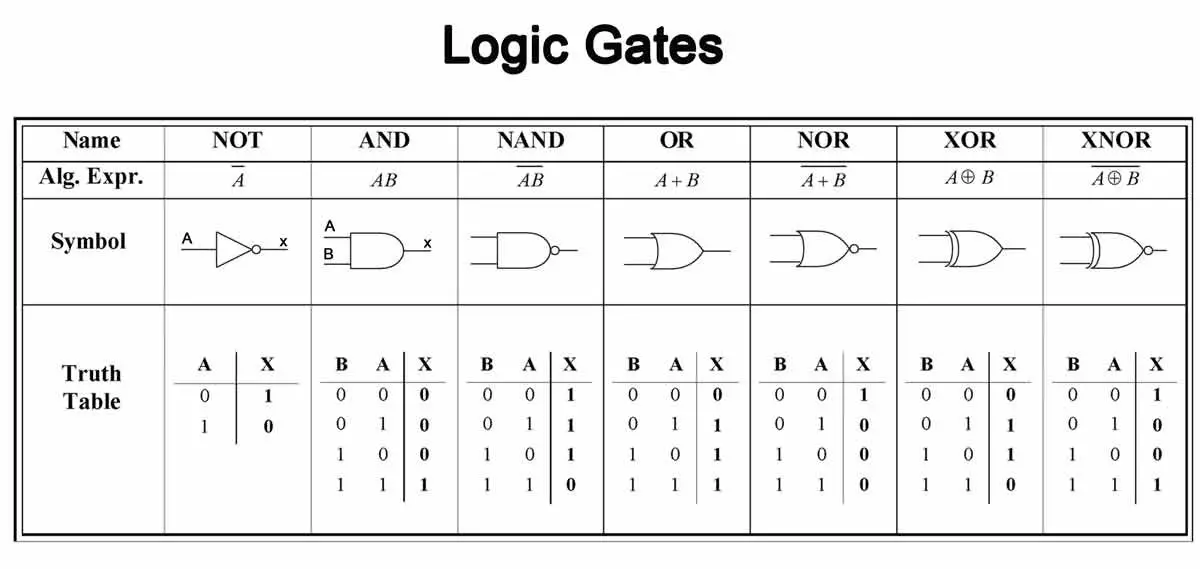
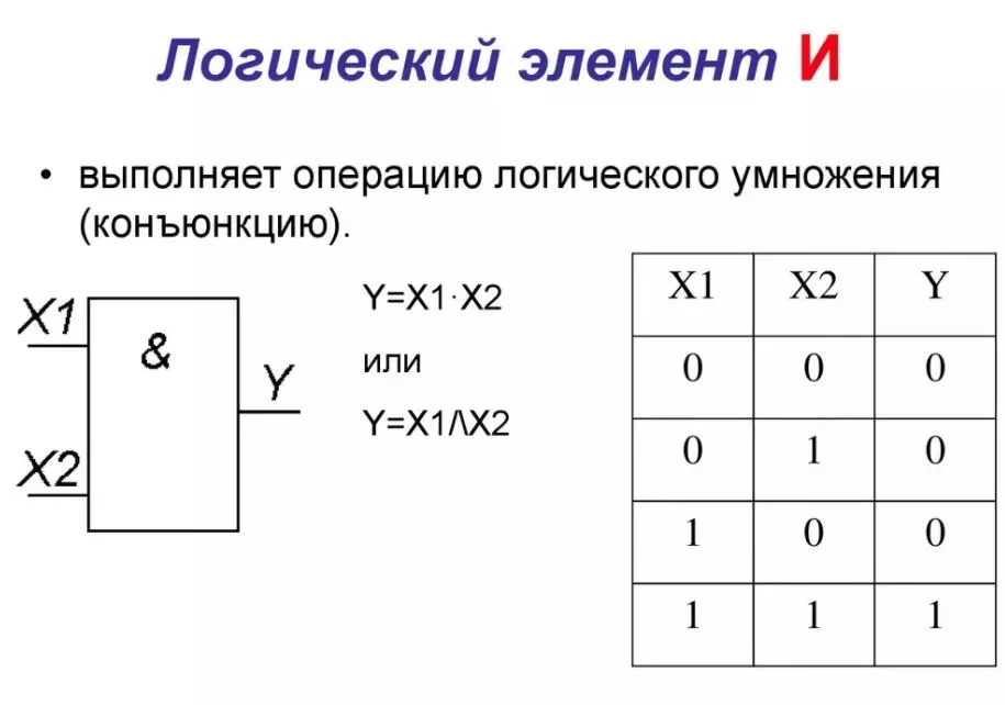
你可能还注意到,异或函数有一个独特的数学符号,看起来像一个圆圈里的加号。许多人使用这个符号来简化表示。此图中的所有逻辑门均为左输入、右输出的方向。另外请注意,这里的输出用“x”符号表示,而非Q,但含义相同。 任何在输入或输出附近看到的小圆圈都表示此处放置了反相器。因此,与非门(NAND)就是将与门(AND)的输出再接入非门(NOT)。有时也需要对一个或多个输入进行反相。所有输入都通过非门反相的逻辑门通常被称为“带气泡的门”。例如,带气泡的与门的函数可表示为-A*-B。真值表 真值表可能是你确定电路需求时的一个良好起点。你只需在表格中映射所有输入和输出。 以下是与门的简单示例: X A B 0 0 0 0 0 1 0 1 0 1 1 1 该门的输出仅在所有输入都为高电平/激活状态时才为高电平/激活状态。 以下是或门的示例: X A B 0 0 0 1 0 1 1 1 0 1 1 1 异或门: X A B 0 0 0 1 0 1 1 1 0 0 1 1 以下是一种多路分配器(解复用器)的真值表: W X Y Z A B 1 0 0 0 0 0 0 1 0 0 0 1 0 0 1 0 1 0 0 0 0 1 1 1 多路分配器是大多数用于寻址和其他功能的选择器电路的基础。它也可用于创建非常复杂的状态机。输入为A和B,输出为W、X、Y和Z。在任何时候只有一个输出处于激活状态。 布尔代数 本节对大多数人来说在很大程度上是可选的。你无需学习相关知识也能完成所有必要操作;但了解其中的数学原理有助于优化设计,减少逻辑门的使用。使用更少的逻辑门意味着占用更少资源,更重要的是电路会更简单,运行速度更快、更稳定。简单的电路在模拟时也会占用更少的CPU时间。 查看最终示例,了解轻松创建多输入与门的好方法。 或许最重要的规则是如何移动取反操作。 如果X等于非A与非B,那么X等于非(A或B),或者非X等于A或B。 通过观察真值表可以看出这是一个或非门;但原始函数被表示为一个带气泡的与门。这两个逻辑门的功能完全相同,但选择哪一个可能取决于你的输入和/或输出。 你可以对某些项进行分组,将每一项取反,再将整个组取反,然后改变运算方式。 另一个例子:如果-X=(A*B),那么X=-(A*B),且X=-A+-B。 XAB100101110011这是与非门的真值表,但我们可以看到它和带非门的或门(bubbled-or)是一样的。 最后一个例子: X = A*B = -(-(A*B)) = -(-A+-B) (第一步成立的原因是A = -(-A),因为两次非运算本质上相互抵消) XAB000001010111 这是标准的与门;有趣的是,我们可以发现与门的功能仅通过或门和非门就能实现。X=-(-A+-B) 这种做法的好处可能不会立即显现,但或门实际上就是一个简单的连接点,其输入与输出相互隔离。将三到四段自动化导线连接在一起,并用非门或缓冲器隔离连接点,就能得到一个简单的多输入或门。 如果对所有输入取反,再对输出取反,就得到了与门!(此时隔离会自行实现) 以下是两个十输入与门。左侧的使用级联与门,右侧的则使用简单的连接点或门。门本身就是导线。
当所有输入均激活时,两个门都处于激活状态。

只要有任意输入为关闭状态,两个门都会处于关闭状态。 计时器、边缘检测器和脉冲发生器 游戏中有一个【时钟】道具,可用于安排自动化操作,但它的功能相当有限。每个时钟每个周期只能激活一次,且激活时间和持续时间都以百分比设置(这很难精确设定)。此外,对于电力系统负载平衡这类工作,时钟可能并不实用。如果电力不足,你或许会尝试按一定间隔为不同电路开关电源,让每个电路都能获得一些运行时间。对于这类任务,可能需要更可控的方法。时钟在其他电路和同步方面也非常有用。我为《缺氧》设计出的最佳方案是将缓冲门、过滤门和非门以环形方式连接起来。
方向并不是特别重要,你可以采用缓冲器>过滤器>非门的顺序,或者过滤器>缓冲器>非门的顺序。两种方式都可行。它们之间的唯一区别是,缓冲器>过滤器>非门的脉冲输出为低电平有效(会产生一个非常短的“关闭”脉冲),而过滤器>缓冲器>非门的脉冲输出为高电平有效(会产生一个非常短的“开启”脉冲)。 有两点需要注意:主时钟输出可以从非门的任意一侧获取,但缓冲器和过滤器之间的部分起到脉冲发生器的作用。其次,信号的总波长将是两种设置的总和。例如,1秒的过滤器和1秒的缓冲器将产生2秒的周期,信号会开启1秒,关闭1秒。如果你将一个设置为3秒,另一个设置为1秒,那么你的信号将每4秒重复一次。你可以从非门的任意一侧获取信号,其中一侧会保持3秒开启、1秒关闭,而另一侧则相反。 这些设置也可用于占空比调节,例如50%开启和50%关闭、25%/75%,以及其他任意比例。 就总波长而言,我发现当总波长低于2秒时,无法获得稳定的结果。它们可能与游戏时间同步,也可能不同步。如果你只需要一个简单的脉冲发生器,只要脉冲持续时间不需要极短,那么将缓冲器或滤波器的输出通过非门连接到其输入即可满足需求。 这是一个不错的边缘检测器。如果提供时钟信号,它可以用作脉冲发生器。
这种设计的另一个优点是它能在上升沿和下降沿都触发。也就是说,当时钟信号从0变为1时会触发输出,当信号变回0时会再次触发。因此,使用我上面提到的简单2秒时钟,这个边沿检测器每秒会发送一个短脉冲。 要使用它检测特定边沿,你需要将其输出与时钟信号进行与运算(用于上升沿检测),或者与反相时钟信号进行与运算(用于下降沿检测)。这样可以确保在信号的每个周期内只触发一次。

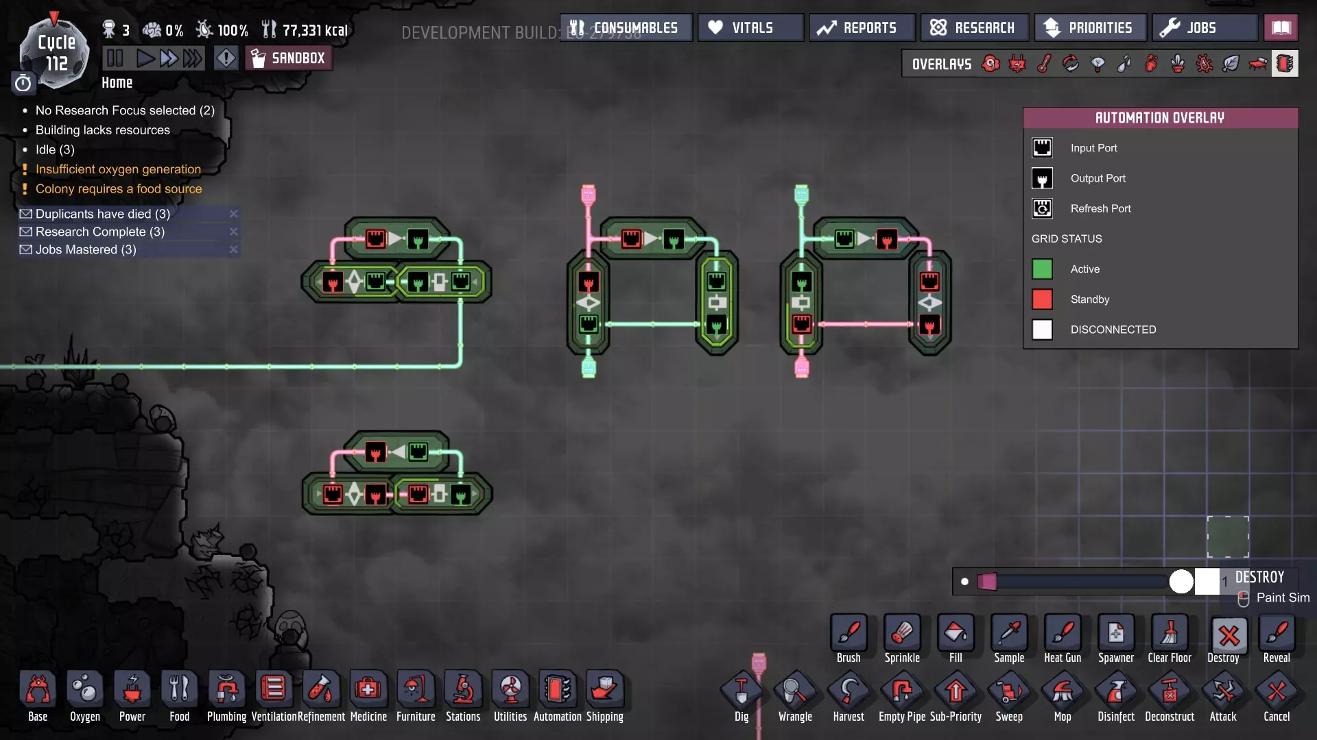
有限状态机:净水器 有限状态机是一个相当通用的概念,但基本上可以概括为: 有限状态机由其状态和转换定义。 它具有有限且可数的状态数量,并且每个状态都有明确的定义。 每个转换连接一个或多个状态。 机器在同一时间只能处于一种状态。 状态通常存储在锁存器或寄存器中。由于游戏包含RS锁存器,这通常是你在游戏中用于存储状态的组件。 我们有一个带有泵的含菌污染水库,该泵将水抽入我们的水箱。 我们的水箱有一个泵,将净化后的水抽到净水筛。让我们先确定流程,我们需要三个独立的阶段: 首先,我们要将含有病菌的水抽入水箱直至注满。我们称之为【注水状态】。 其次,我们要加热水直至病菌全部消灭。我们称之为【加热状态】。 第三,我们要将水抽出直至水箱排空。我们称之为【排水状态】。 这意味着我们至少需要三个传感器。 现在让我们描述一下目前的系统: 我们将使用满水传感器、空水传感器和病菌传感器作为输入设备。 输出设备则为水泵和加热器。 我们本可以不将加热器作为输出设备,但当液位较低时它可能会损坏自身;因此我们会关闭加热器以节省电力,同时避免频繁维修。
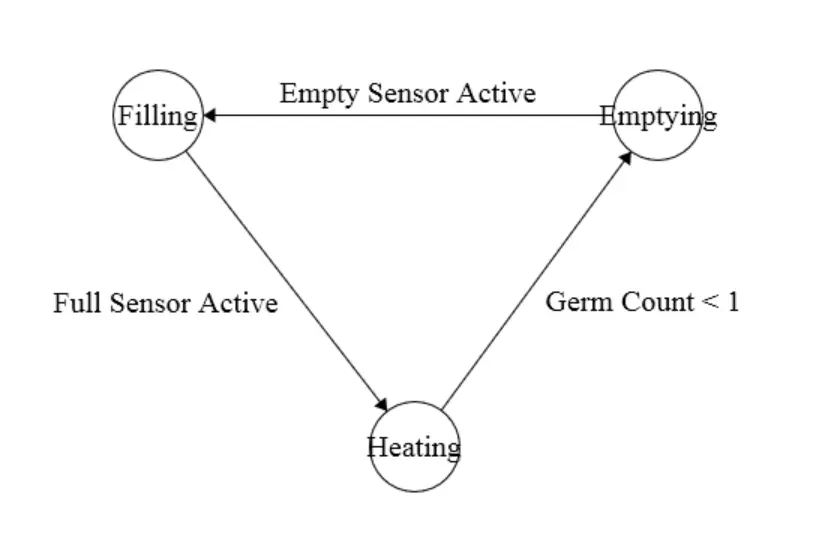
因此,细菌传感器指示我们切换到排空状态,空传感器指示我们切换到填充状态,满传感器指示我们切换到加热状态。RS锁存器非常适合此任务,因为我们的状态机只需单向转换。这是最终产品。
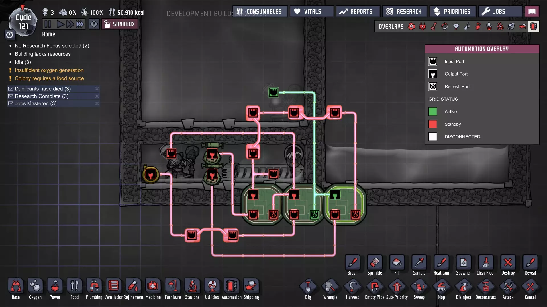
你可以让加热器和注水泵在同一状态下运行,这样就能将机器减少到两种状态;不过,机器就不会像现在这样多功能了。如果你使用细菌传感器来触发状态转换,水箱可能在未满时就开始排水。如果你使用满水传感器来触发状态转换,系统可能会泵出带菌水。两者相比,其中一种问题相对较小。 应用自动化设计 在上一节中,我们设计了一个水净化装置。不过你可能已经注意到,我们只需要三种状态,这仅需两位就能处理,但我们的设计却使用了三位状态机。我们当前的设计有三位和三种状态: 001 表示【加热】 010 表示【排空】 100 表示【填充+加热】 这可以“简化”为 00=加热、01=排空、10=填充+加热。 因此,如果 B 为 0,则加热器应运行。 如果 A 为 1 且 B 为 0,则储罐应填充。 如果 A 为 0 且 B 为 1,则储罐应排空。 我们可以推测,由于加热器需要 1 才能激活,我们可能需要对此稍作调整,以省去一个额外的逻辑门。让我们将所有状态取反——11=加热、10=排空、01=填充+加热。 现在,如果 B 为 1,加热器应运行。 接下来的问题是“我们如何决定何时置位和复位锁存器?” 目前我们有一个空传感器、一个细菌传感器和一个满传感器。回顾我们的状态图,无论我们如何表示状态,它都应仍然成立。 如果空传感器触发,系统应转换到填充状态。因此,它将重置锁存器A并设置锁存器B。 满传感器将设置锁存器A和锁存器B(尽管严格来说不需要设置锁存器B,因为我们的状态机只有单向转换,但这样做始终是良好的实践)。 无菌传感器将设置锁存器A,并重置锁存器B(这里情况类似,但这次涉及的是锁存器A)。 最终结果是减少了一个RS锁存器,但增加了两个额外的与门(用于锁存器的输出)。因此,在这种情况下,简化的唯一原因是如果RS锁存器特别昂贵。然而,在更复杂的电路中(3位可以处理多达8种状态),空间和材料的节省会非常显著。 新增内容 这是一个8位多路复用器:
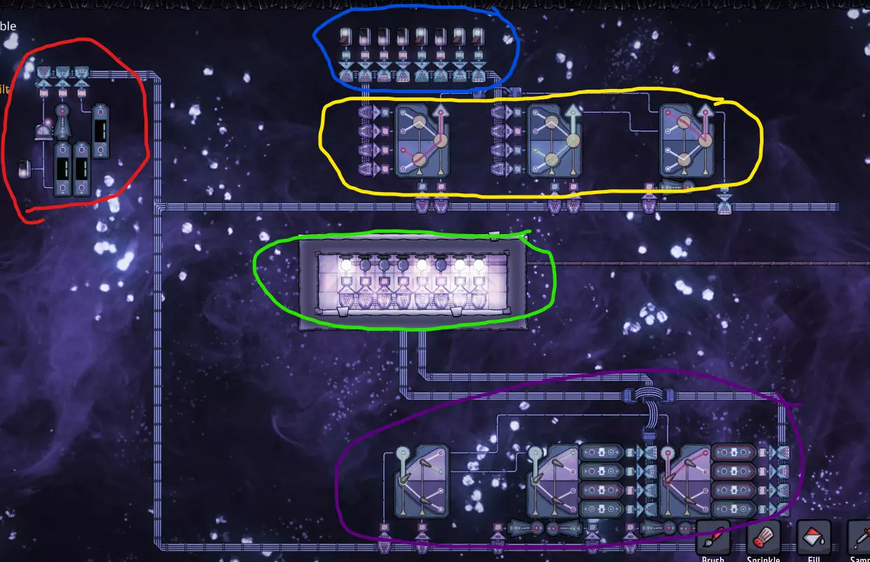
我对其各个部分进行了圈注并分解如下: 红色 - 控制时钟 蓝色 - 输入开关(可能是传感器或其他设备) 黄色 - 多路复用器(mux) 紫色 - 解多路复用器(demux) 绿色 - 输出端,我使用了指示灯(但同样也可以是其他设备) 接下来,我们来了解各个组件。控制时钟:

这是一个计时器(新部件之一),设置为0.1秒开启、0.1秒关闭,产生的脉冲宽度正好是一个滴答。开关可以让我强制将计时器输出设为绿色,暂停时钟。另外两个部件由串联的一个和两个计数器组成,每个都设置为在正常模式下计数到2。结果是一个分频器。非门用于适当的信号时序。最长的脉冲延迟为0,因此不需要任何非门。中等脉冲需要一个滴答的延迟(以考虑较长脉冲上的额外计数器),因此使用一个非门。计时器作为最短的脉冲,理论上需要两个滴答的延迟……但两个非门会让你回到起点(360度相移)……所以它也不需要任何非门。如果你将三个时钟位视为从左到右依次为最低有效位到最高有效位……那么它本质上是从000计数到111(即从0到7)。 关于输入和输出,我就不多做说明了,它们各自的作用都相当直观。我使用了新的4线总线来简化线路并保持整洁……但这和直接布设8根独立线路没有本质区别。 至于多路复用器:
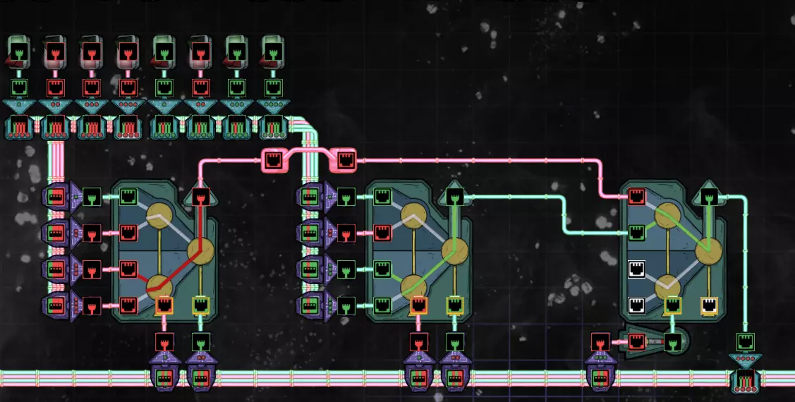
每个信号分配器有四个数据输入端(此处靠左排列)、两个选择器位输入端(位于底部)和一个输出端。其工作方式类似于分支路径。仔细观察动画可以帮助你准确了解其工作原理。左侧位控制左臂,右侧位控制右臂。当为绿色时,它们选择下方的输入;当为红色时,它们选择上方的输入。由于有两个选择器,因此最多可以有四个数据输入。如果从上到下编号(按图示旋转方向),可以将它们视为00、01、10和11。我使用时钟的前两位来控制前两个分配器,从而实现总共8个数据输入。这意味着这两个分配器会不断在所有四个输入之间切换。无论当前选择的是哪个输入,都会被发送到输出端。每个输出会被发送到下一级的前两个输入,其选择位是我们时钟的第三位;因此,每4个时钟周期,它会切换所使用的输入。最终结果是,所有8个输入会被依次读取,每个输入会在总线的第4位上精确发送1个时钟周期。注意,时钟的第三位在被输入到第二级多路复用器(mux)之前添加了一个非门,这是为了补偿前一级多路复用器造成的延迟……我们需要时钟与数据在传输路径上的位置相匹配。 对于多路分配器(demux):
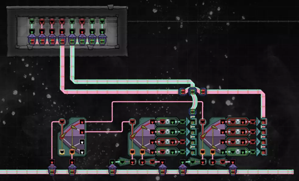
这基本上与多路复用器相反。数据位(位4)被输入到顶层解复用器(最左侧的那个)的输入端,然后第三个时钟位被输入到选择器的最右侧输入位。其输出将每4个时钟周期切换一次。这两个输出被向下输入到相应的下层解复用器。下层解复用器(最右侧的两个)的选择位(从左到右)分别是时钟的第二位和第一位。请注意,这两个位在下层有一个时钟周期的延迟,以补偿第一个解复用器造成的延迟。信号选择器输出输入的任何内容;因此,其每个输出的“激活”时间应为1个时钟周期……依次经过所有8个输出。注意,未连接的数据输出始终显示为红色……这仅表示它是高电平有效配置。例如:当某个输出被选中时,其颜色可能为红色或绿色,具体取决于输入……所有其他输出都将为红色。这意味着我们需要缓冲门来获得一致的逻辑输出。这些缓冲器都设置为0.8秒(或8个滴答)。这意味着如果某个输出仅在一个滴答内变为绿色,缓冲器的输出将保持绿色,直到时钟信号有时间循环回到它……此时它将重新填充缓冲器。如果在某个时刻它变为红色,缓冲器将在其下一个窗口到达后相应地更新。 最终结果: 我已使用开关对二进制字节10001011进行了编码。这个字节通过第4根线串行传输到指示灯。得益于多路复用技术,所有8位数据都能通过单根线传输。你也可以将它们用于其他方式,并且它们还具有一些逻辑应用(尤其是对于编码器/解码器),因为它们的功能类似于级联与门。以多路复用器为例,如果顶部数据位为绿色,其他数据位为红色,选择器就像一个组合两个开关位的与非门,只有当两个输入都关闭时,输出才会开启。中间的两个数据位会改变其行为,根据哪个数据位处于活动状态,其行为基本上是S1异或非S2或非S1异或S2。如果最后一个数据位为高电平,选择器就像一个普通的与门。因此,你可以用它来构建一些相当复杂的情境逻辑。另一个例子,如果第二个和第四个数据位为绿色,那么输出就只是S1,不管S2是什么。还有其他组合数据位和开关位的方式可以获得不同的行为,多路分配器也是如此。